Electronic Project
September - December 2020
My Electronics I class introduced basic electronic concepts using hands-on projects. We explored basic circuit methods by building breadboards, creating Printed-Circuit-Boards (PCBs), and using Arduinos and Raspberry Pis to control them. I took this course remotely, so it was a little more difficult for me to get a hold of all of the materials and assemble correcting. Nonetheless, it was really rewarding to have hands-on experience with electronics through these projects.
Voltage Regulator PCB

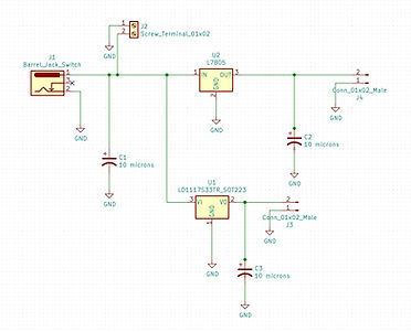
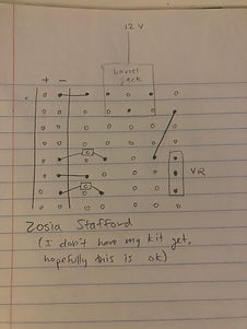

The goal of this project was to create a voltage regulator that would receive 12 volts from the wall and output 5 and 3.3 volts. I started by brainstorming what my setup would look like on a breadboard; then I built it on the breadboard, using two voltage regulator chips and three capacitors. After confirming that it worked as intended, I began to design a PCB for it. I created a schematic based on my breadboard, loaded in the correct components, and layed it out on a PCB. I made sure that this chip could fit on top of my breadboard, where it would be useful for future projects. Because I was taking this course remotely, I did not have a high quality solder to use, but I learned some good lessons on soldering.
H-Bridge Motor Driver PCB
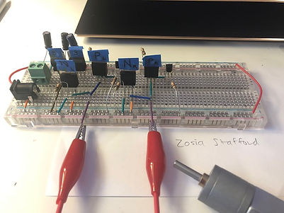


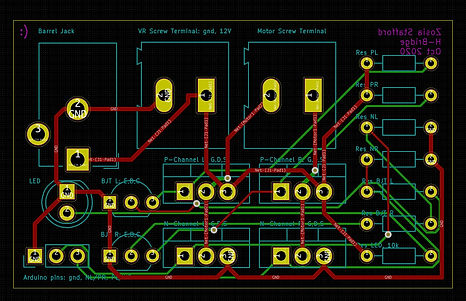
This project built off of the skills I learned with the first project, and took it further. The goal was to build an H-bridge, which is a chip used to control motor direction using MOSFETs and BJTs. This was a good lesson in how to control high powered tools using low power.
Arduino Game


